- 您现在的位置:买卖IC网 > Sheet目录970 > CPC1014N (IXYS Integrated Circuits Division)RELAY OPTOMOS 400MA SPST 4-SOP
�� �
�
�I� NTEGRATED� C� IRCUITS� D� IVISION�
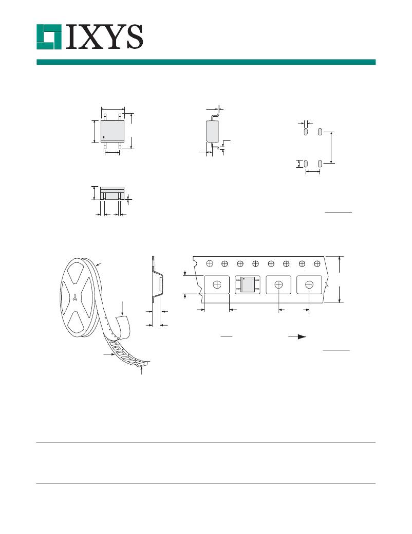
�MECHANICAL� DIMENSIONS�
�CPC1014N�
�CPC1014N�
�3.810� ±� 0.076�
�4.089� ±� 0.203�
�(0.161� ±� 0.008)�
�6.096� ±� 0.102�
�0.200� ±� 0.025�
�(0.008� ±� 0.001)�
�Recommended� PCB� Land� Pattern�
�0.60�
�(0.0217)�
�(0.150� ±� 0.003)�
�(0.240� ±� 0.004)�
�0.432� ±� 0.127�
�(0.017� ±� 0.005)�
�5.60�
�Pin� 1�
�2.54� Typ�
�(0.100� Typ)�
�2.184� Max�
�(0.086� Max)�
�1.02� ±� 0.025�
�(0.040� ±� 0.001)�
�1.30�
�(0.0512)�
�2.54�
�(0.10)�
�(0.2205)�
�Lead� to� package� standoff:�
�0.0637� ±� 0.0383�
�(0.0025� ±� 0.0015)�
�0.762� ±� 0.102�
�(0.030� ±� 0.004)�
�0.381� TYP.�
�(0.015� TYP.)�
�Dimensions�
�mm�
�(inches)�
�CPC1014NTR� Tape� &� Reel�
�330.2� Dia�
�(13.00� Dia)�
�Top� Cover�
�Tape� Thickness�
�0.102� Max�
�(0.004� Max)�
�B� 0� =4.70�
�(0.185)�
�W=12.00�
�(0.472)�
�K� 0� =2.70�
�(0.106)�
�A� 0� =6.50�
�(0.256)�
�P=8.00�
�(0.315)�
�K� 1� =2.30�
�(0.091)�
�User� Direction� of� Feed�
�Dimensions�
�Embossed�
�Carrier�
�Embossment�
�mm�
�(inches)�
�NOTE:� All� dimensional� tolerances� per� Standard� EIA-481-2� except� as� noted�
�For� additional� information� please� visit� our� website� at:� www.ixysic.com�
�IXYS� Integrated� Circuits� Division� makes� no� representations� or� warranties� with� respect� to� the� accuracy� or� completeness� of� the� contents� of� this� publication� and� reserves� the� right� to� make�
�changes� to� specifications� and� product� descriptions� at� any� time� without� notice.� Neither� circuit� patent� licenses� nor� indemnity� are� expressed� or� implied.� Except� as� set� forth� in� IXYS� Integrated�
�Circuits� Division’s� Standard� Terms� and� Conditions� of� Sale,� IXYS� Integrated� Circuits� Division� assumes� no� liability� whatsoever,� and� disclaims� any� express� or� implied� warranty,� relating� to� its�
�products� including,� but� not� limited� to,� the� implied� warranty� of� merchantability,� fitness� for� a� particular� purpose,� or� infringement� of� any� intellectual� property� right.�
�The� products� described� in� this� document� are� not� designed,� intended,� authorized� or� warranted� for� use� as� components� in� systems� intended� for� surgical� implant� into� the� body,� or� in� other�
�applications� intended� to� support� or� sustain� life,� or� where� malfunction� of� IXYS� Integrated� Circuits� Division’s� product� may� result� in� direct� physical� harm,� injury,� or� death� to� a� person� or� severe�
�property� or� environmental� damage.� IXYS� Integrated� Circuits� Division� reserves� the� right� to� discontinue� or� make� changes� to� its� products� at� any� time� without� notice.�
�Specification:� DS-CPC1014N-R03�
�?Copyright� 2012,� IXYS� Integrated� Circuits� Division�
�OptoMOS?� is� a� registered� trademark� of� IXYS� Integrated� Circuits� Division�
�All� rights� reserved.� Printed� in� USA.�
�12/13/2012�
�6�
�发布紧急采购,3分钟左右您将得到回复。
相关PDF资料
CPC1016N
RELAY OPTOMOS SP-NO 100MA 4-SOP
CPC1017N
RELAY OPTOMOS SP-NO 100MA 4-SOP
CPC1018N
RELAY OPTOMOS 600MA 4-SOP
CPC1020N
RELAY OPTOMOS 1200MA 4-SOP
CPC1025N
RELAY OPTOMOS 120MA 4-SOP
CPC102K
CORD PATCH COMBINATION 6 FEET
CPC1030N
RELAY OPTOMOS SP-NO 120MA 4-SOP
CPC1035N
RELAY OPTOMOS SP-NO 100MA 4-SOP
相关代理商/技术参数
CPC1014NTR
功能描述:固态继电器-PCB安装 1-Form-A solid state relay - 4-Pin
RoHS:否 制造商:Omron Electronics 控制电压范围: 负载电压额定值:40 V 负载电流额定值:120 mA 触点形式:1 Form A (SPST-NO) 输出设备:MOSFET 封装 / 箱体:USOP-4 安装风格:SMD/SMT
CPC1016N
功能描述:固态继电器-PCB安装 1-Form-A solid state relay - 4-Pin RoHS:否 制造商:Omron Electronics 控制电压范围: 负载电压额定值:40 V 负载电流额定值:120 mA 触点形式:1 Form A (SPST-NO) 输出设备:MOSFET 封装 / 箱体:USOP-4 安装风格:SMD/SMT
CPC1016N_1
制造商:CLARE 制造商全称:Clare, Inc. 功能描述:4-Pin SOP OptoMOS? Relay
CPC1016NTR
功能描述:固态继电器-PCB安装 1-Form-A solid state relay - 4-Pin RoHS:否 制造商:Omron Electronics 控制电压范围: 负载电压额定值:40 V 负载电流额定值:120 mA 触点形式:1 Form A (SPST-NO) 输出设备:MOSFET 封装 / 箱体:USOP-4 安装风格:SMD/SMT
CPC1017
制造商:CLARE 制造商全称:Clare, Inc. 功能描述:4 Pin SOP OptoMOS Relays
CPC1017N
功能描述:固态继电器-PCB安装 SPNO RELAY
RoHS:否 制造商:Omron Electronics 控制电压范围: 负载电压额定值:40 V 负载电流额定值:120 mA 触点形式:1 Form A (SPST-NO) 输出设备:MOSFET 封装 / 箱体:USOP-4 安装风格:SMD/SMT
CPC1017N_1
制造商:CLARE 制造商全称:Clare, Inc. 功能描述:4-Pin SOP OptoMOS? Relays
CPC1017NTR
功能描述:固态继电器-PCB安装 1-Form-A solid state relay - 4-Pin
RoHS:否 制造商:Omron Electronics 控制电压范围: 负载电压额定值:40 V 负载电流额定值:120 mA 触点形式:1 Form A (SPST-NO) 输出设备:MOSFET 封装 / 箱体:USOP-4 安装风格:SMD/SMT